How to Build a Robot Car
How to Build a Robot Car
Have you ever wanted to see your own robot car roving around? Build one with a few electronics parts, an Arduino microcontroller, and copy-paste programming. Even if you've never tried a project like this before, take the chance to practice your soldering and get familiar with some basic code.
- Two motors
- Two wheels
- Arduino microcontroller board (the Arduino Uno is a good choice for beginners)
- Motor driver shield or motor driver circuit (found in remote-controlled toy cars)
- Battery holder and 6 volts of batteries (e.g. four AA batteries)
- Chassis: a sheet of acrylic or plexiglass, about 6.5 x 4.5 inches (16.5 x 11.5cm)
Glue on the battery holder. Add a dollop of hot glue to the top side of the chassis, between the wheels. Press the battery holder here and let set.
Attach the motor driver circuit. Position the motor driver circuit near one side of the chassis, with the wires overhanging the edge.
Position the Arduino. Glue the Arduino onto the
chassis, tucked opposite the driver circuit. When positioning it, make
sure you have access to the socket for plugging the Arduino into the
computer.
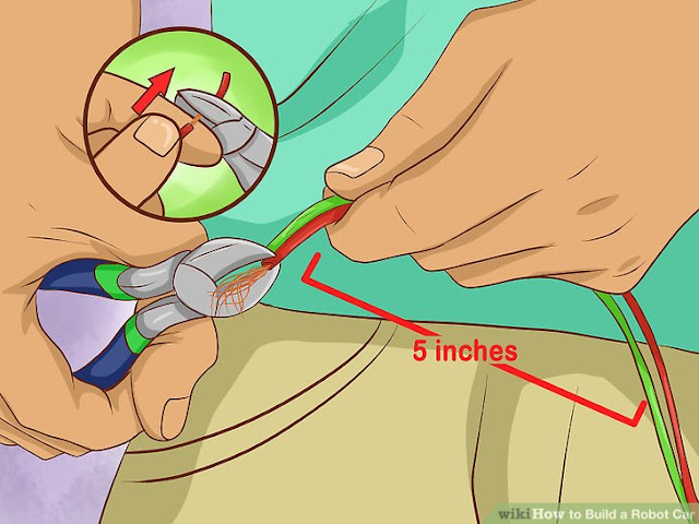
Cut four lengths of wire. You'll need four pieces of
insulated wire, with each end stripped. Read this section first to find
out how each wire is connected, so you can cut each one to the right
length. Typically, each wire should be about 5 inches (13cm) long.
Solder two wires onto one motor. Solder one wire onto each of the two motor pins.
- Read our guide on soldering electronics first if you don't have much soldering experience.

Solder the other ends to the motor driver. Find the motor pins on the motor driver circuit that are labeled m1 and m2. Solder the other ends of the two wires onto these pins.
- If your driver does not have these labels, look for a diagram of your motor driver online.
Repeat for the other motor. Solder the other two
wires to the two pins on the second motor. Solder the other ends of
these wires onto the driver pins labeled m3 and m4.
Connect the battery holder. The battery holder should have two attached wires, one positive (red) and one negative (black). Connect these as follows:
- Connect the positive wire to the Vin pin on the Arduino
- Connect the negative wire to the Gnd (ground) pin on the Arduino
Connect the motor driver circuit. The motor driver has two wires as well. Connect these to the Arduino, making contact with the wires from the battery holder:
Upload the following code. Type the following program
into Arduino. Once finished, upload it into your circuit. This code
will cause your car to move forward for 5 seconds, take a right turn,
and move forward for another 5 seconds:
- Connect the positive pin on the motor driver circuit to the Vin pin on the Arduino.
- Connect the Gnd pin on the motor driver circuit to the Gnd pin on the Arduino.
- If you have difficulty identifying the Arduino pins, find an online guide specific to your model

Cut four wires of equal length. These will connect the Arduino and the motor driver circuit.
Solder the wires. Solder each wire to one pin on the integrated circuit. Take care not to make contact with a second pin. Solder as follows:
- Solder one wire on to the LEFT pin shown in the IC pin diagram. The LEFT pin is 7th from the top.
- Solder a wire on to the RIGHT pin shown in the IC pin diagram. The RIGHT pin is 6th from the top, just above "left."
- Solder a wire on to the BACKWARD pin shown in the IC pin diagram. The BACKWARD pin is the 10th pin, exactly opposite "left."
- Solder a wire on to the FORWARD pin shown in the IC pin diagram. The FORWARD pin is just above "backward," exactly opposite "right."
Connect the wires to the Arduino. Taking care not to confuse the wires, attach each one to the Arduino as follows:
- Connect the LEFT wire to pin 5 of the Arduino.
- Connect the RIGHT wire to pin 6.
- Connect the BACKWARD wire to pin 9.
- Connect the Forward wire to pin 10.
Check your wiring. Examine all your wiring closely. Make sure there are no unintentional connections causing a short.
Connect Arduino to a computer. Plug the Arduino circuit into your computer. Open the Arduino software. This allows you to program your car's movements.
- Arduino software is available for free online.
Start the car. Set the car on a flat surface. Put in
the batteries and watch it go! If your battery holder has a switch,
flick it to turn the car on and off.
- You can add your own switch by connecting the positive wire of the battery holder to the center pin of an SPST (single pole singe throw) switch. Connect the other pin of the switch to the Vin pin on the Arduino.
Play around with the code. Change the values in the
code and upload your new program to change the behavior of your car. Try
changing the numbers after "delay," or see what happens when you change
a LOW to a HIGH or vice versa. Just make sure never to set both pins of
a single motor on HIGH at the same time.


Comments
Post a Comment